It would be a plus if the Wi-Fi system had the ability to detect third-party access points and somehow deal with them. For example, if an intruder sets up Wi-Fi with an SSID identical to yours, he will be able to intercept the password when the user tries to connect to the network. Basic functionality:

- Beamforming
- The Basics of Beamforming
- History of Beamforming
- How beamforming works
- MU-MIMO technology from the inside out
- Beamforming (adaptive beamforming)
- Balancing the load
- Antennas. Beating the coverage area into sectors physically.
- Implicit Beamforming
- What is a 5G network
- Basics of 5G
- Millimeter Waves.
- Small Cell
- How to choose equipment
- How and where to place the access points
Beamforming
Anyone can try throwing a rock into the water, there will be waves spreading sideways. If you throw another rock, the two types of waves will overlap. If you throw more rocks, those circular waves will break because they interfere with each other. This is similar to today's wireless interference: so many wireless devices (routers or access points) are spreading signals all over the area, and these signals are like waves interfering with each other. The more of them, the more unstable your Internet connection will be, causing problems.
Today's wireless devices often promise "beamforming" technology – Beamformingto improve Wi-Fi reception and reduce interference. But what is beamforming, how does it work, and is it really useful?
The Basics of Beamforming
In a very simplified explanation, beamforming has to do with focusing the Wi-Fi signal in a certain direction.
Traditionally, when your router/access point transmits a Wi-Fi signal, it transmits data in all directions. When forming a beam, the router detects where your device – laptop, smartphone, tablet or whatever – is located and projects a stronger signal in that particular direction.
Beamforming promises a faster, stronger Wi-Fi signal with more range for each device. Instead of just broadcasting in all directions, the router/access point tries to broadcast the wireless data intended for the device, which is optimal for the device.
So, the end result of beamforming is a better Wi-Fi signal for your devices.
History of Beamforming
A bit of backstory: Beamforming was actually an optional feature of the older 802.11n standard, but the IEEE (the international body which sets these standards) had not clarified exactly how it was to be implemented. And it could be that you bought a router and it uses one implementation, but the Wi-Fi adapter in your laptop uses another, in which case beamforming won't work.
Some manufacturers developed their own 802.11n kits, but they tended to be expensive and not widely in demand in the market.
Beamforming focuses the signals exchanged between the Wi-Fi router and the clients to which it is connected.
The IEEE did not make the same mistake with 802.11ac. Companies making 802.11ac-enabled equipment are not required to implement beamforming, but if they do, they only do so according to an established specification. This ensures that each company's equipment is compatible. If one device (such as an access point) supports beamforming and another (such as a Wi-Fi adapter in a laptop) does not, they will still work together. Only the Beamforming technology will not be used.
Beamforming makes better use of the wireless network's bandwidth and increases its range. This, in turn, improves video streaming, voice quality and other bandwidth, latency and jitter-sensitive applications.
Beamforming is made possible by transmitters and receivers that use MIMO (multiple-in, multiple-out) technology: data is sent and received using multiple antennas to increase throughput and range. MIMO was first introduced by 802.11n, and it remains an important feature of 802.11ac and 802.11ax. MIMO can operate in 1×1, 2×2 and 3×3, the latter meaning support for 3 spatial streams for transmitting and receiving.
How beamforming works
Wireless routers (or access points) and wireless adapters that do not support beamforming broadcast data in all directions. Think of a lamp without a lampshade as a wireless router: the lamp (transmitter) emits light (data) in all directions.
The devices that support beamforming focus their signals on each client, transmitting data in such a way that more data reaches the target device rather than being radiated into space. Now let's put a lampshade on the lamp (wireless router) to reduce the amount of light (data) being radiated in all directions. Let's make holes in the lampshade so that concentrated beams of light travel to specific locations (your Wi-Fi clients) in the room.
If the Wi-Fi client also supports beam shaping, the router and the client can exchange information about their respective locations to determine the optimal signal path. The device that generates the beam and its signals is called a beamformer, and any device that receives the signals generated by the beam is called a beamformee.
The signals coming from the router's antennas are calibrated with the necessary phase and amplitude offsets, and they experience constructive (amplifying) interference directly in the receiving antenna area of the subscriber equipment, while in the other directions destructive (canceling) interference occurs.
The router sends a probing signal to the client from all of its antennas. The client responds to the router with what it has seen and sends a set of complex matrix with location parameters, phase shift and signal amplitude.
MU-MIMO technology from the inside out
In 2008, the 802.11n standard introduced multi-in multi-output (MIMO) technology designed to increase Wi-Fi throughput between access points and client devices. For MIMO to work, two wireless stations (i.e. both the access point and the client device) must have multiple antennas that are identical and physically separated by a fixed distance from each other so that there is no phase difference at the operating wavelength.
The spatial flow is the set of data sent by the transmitting antennas, which can be mathematically reconstructed at the receiver antennas. In MIMO, each spatial stream is sent from different antennas in the same frequency channel as the transmitter. The figure below illustrates this for the case of two streams.
The receiver receives each stream on an identical radio circuit. Because it knows the phase offsets of its own antennas, it can use mathematical signal processing techniques to reconstruct the original streams. To increase the bandwidth, the number of streams must be increased. Each spatial stream contains a set of unique data, and the number of independent spatial streams is limited by which Wi-Fi device has the smallest number of radio circuits.
Typically, this limitation is the client device: because each radio circuit (antenna) consumes power and requires space for placement. This is why most mobile smartphones and tablets can only support single stream or dual stream communications, and even high-performance laptops and PCs typically only support up to three streams.
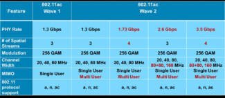
In the first wave of 802.11ac, bandwidth was not only increased through the use of MIMO, but other mechanisms were used as well:
However, the overall bandwidth in any frequency band is "finite" and this imposes its own limitations. The wider the channel, the more susceptible it is to interference.
Beamforming (adaptive beamforming)
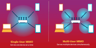
Multiuser MIMO (MU-MIMO) increases channel bandwidth by transmitting data to multiple clients simultaneously. But there is another effective technology – beamforming in the downlink – TxBF.
TxBF was first introduced in 802.11n but has not been widely adopted. While MIMO sends different spatial streams from each antenna, beamforming sends the same stream from multiple antennas with a phase shift.
The router sends service information to the client from all of its antennas, and the client necessarily responds to the router with a matrix that indicates what it has seen from each of the antennas. The router's software calculates the approximate location of the client and makes adjustments to all of its transmitters so as to maximize the signal at the client.
For example, to eliminate fading at one of the antennas, the phase shift is changed or the signal amplitude is increased to pass an obstacle. If a signal from different antennas comes in-phase and with the same power, it adds up – this concept is called constructive interference. In this case, by increasing the power of the signal increases the data rate and the maximum distance to the client. And vice versa, if two signals with the opposite phase they are canceled, and the resulting signal amplitude can be equal to zero – this is called destructive interference of radio waves.
Forming a radiation pattern requires the use of a phased antenna array in which there are many of the same antennas and they are spaced a fixed distance apart (to work in antiphase).
Balancing the load
Unfortunately, as such, there is no forced roaming from the base station in WiFi to this day. And this is a big problem for high-density WiFi. That is, it is up to the subscriber to decide which base station to connect to. There are protocols, so-called "fast authorization" implemented in standards 802.11k-r. This standard allows for seamless and rapid switching of subscribers between bases, giving the client a "list" of the nearest access points in a special packet / flag, which is added to the basic authorization data.
But it does not help to balance the load. In centralized controllers like UniFi, it is possible to control the power of the access point, as well as the channels on which it operates. It is also possible to forcibly disconnect subscribers. Basically, it is a set of crutches that will not fully replace roaming, BUT – combined with other technologies, it helps improve the overall picture when working in high-density WiFi.
Antennas. Beating the coverage area into sectors physically.
It's simple enough here. Sector antennas are especially effective when the concert venue is open and has no walls from which the radio signal will be reflected. Sector antennas allow dividing the serviced area between the wireless access points into sectors, which is one of the simplest and most effective ways of load balancing. Everything happens at the physical level here.
The radio signal takes the form of a wide beam that captures a specific space. Притом, деление достаточно точное (при использовании хороших антенн), в двух метрах сигнал от одной точки доступа слабеет в разы, а другой, напротив, в аналогичных значениях увеличивается, заставляя абонента выбирать именно ту точку доступа, которая предусмотрена по проекту.
Implicit Beamforming
The initial assumption of implicit beamforming is to free STAs from providing CSI feedback. Implicit beamforming leverages the reciprocity of a time division duplex (TDD) system. Reciprocity states that the uplink CSI and downlink CSI on a frequency band are identical. In this way, uplink CSI is directly applied to the downlink channel for beamforming.
Implicit beamforming is no longer supported from the 802.11ac standard due to its complexity.
As defined in 802.11n, the implicit beamforming process consists of CSI sounding and feedback, as shown in the following figure.
In explicit beamforming, STAs provide actual CSI feedback; in implicit beamforming, the uplink CSI and downlink CSI are considered identical but the downlink CSI is not the actual CSI.
In practice, applying the uplink CSI to the downlink channel may be unable to achieve the desired effect due to the difference between the uplink and downlink channels. To ensure the beamforming effect, STAs still need to obtain the downlink CSI and offer it to the AP, assisting the AP in channel calibration. The calibration process is as follows:
- An AP sends a Calibration Start frame, which is also a Sounding Start frame, to a STA.
- After receiving the Calibration Start frame, the STA sends a response frame (Calibration Response frame + Sounding Response frame) to the AP, assisting it in estimating the uplink channel.
- Based on the response frame, the AP estimates the uplink channel and sends a calibration frame (Sounding frame + CSI Feedback frame) to the STA. This enables the STA to collect downlink CSI and requests the STA to provide CSI feedback to the AP.
 802.11ac
 MIMO
MIMO MU-MIMO
 Smart Antenna
 WLAN
WLAN WiFi
WiFi WiFi 6
What is a 5G network
One of the key things to consider when designing a 5G network is that when it reaches full capacity with full bandwidth, wired network connections will no longer be needed. Devices such as HDTVs, security systems, smart devices, auto-controlled cars and many others will no longer need cables to provide communications or other types of entertainment services.
The fifth-generation wireless network is the latest iteration of cellular technology. It was designed by developers to make the wireless network even faster and more responsive. If you're wondering what it means to make the Internet even faster, imagine downloading files, but not tens of MB/s, but tens of GB/s. It's a very different experience, isn't it? Latency is predicted to be less than 1ms or even less for uses that require instant response.
To better understand what 5G is all about, it's not enough to know that it only increases speed, capacity and latency. A fifth-generation network offers many features, such as network splitting. This feature gives the network provider the ability to create multiple virtual networks in a 5G system. Network sharing offers many great features for the user. With the advent of the Internet of Things and autonomous cars, it will become possible to distribute network connections more precisely among all devices.
Basics of 5G
While the field of fifth-generation networks is still unusual for many scientists, there are a certain number of entirely new technologies that have begun to develop as the foundations of 5G.
The main technologies that make up the 5G network are:
Millimeter Waves.
You can probably safely say that a 5G network and millimeter waves can be used synonymously, but there are still some important takeaways to be aware of. As just part of what 5G technology will use, millimeter waves combined with "lower band" and "below 6 GHz" frequencies will provide higher data rates with a host of other benefits for customers.
The term mmWaves itself refers to a certain part of the radio frequency spectrum, which is between 24 GHz and 100 GHz. Both of these frequencies have one thing in common – their wavelengths are very short. The goal that mmWaves technology aims to achieve is to use the unused wavelength spacing to significantly increase the bandwidth available on the network. The problem with current 4G radio frequencies is that they are heavily loaded with many other signals, and mmWaves aims to fix that. On the other hand, while mmWaves can contribute to one of the main goals of a 5G network – a significant increase in data rates – the transmission distance gets a little shorter.
To summarize by frequency, lower frequencies can benefit from increased speeds, while higher frequencies increase distance but provide slower transmissions. The reason scientists chose millimeter waves for 5G technology is because they can cover small, densely populated areas, which will be one of the biggest advantages for many cities.
Small Cell
Another key technology that plays an important role in 5G technology is Small Cell. While the existing traditional network infrastructure has many limitations, 5G technology aims to reinforce them. This is an achievable goal using Small Cell technology. It is a low-power, short-range wireless data transmission system or base stations covering a small geographic area. It can also be used for indoor and outdoor applications.
How to choose equipment
Choosing Wi-Fi equipment, even for your home, is no longer a simple matter. Depending on your tasks and budget, you can briefly determine for yourself what you need and make a choice based on that. Below we will go over the basic technologies of wireless networks.
A brief look at the basic IEEE 802.11 standards
- IEEE 802.11b (a very old standard which is unlikely to be needed for specific devices;)
- IEEE 802.11g (obsolete standard, but may be required for specific devices);
- IEEE 802.11n (obsolete standard, many devices still run on it);
- IEEE 802.11ac (a modern standard for most new devices);
- IEEE 802.11ax (a relatively new standard, with room for the future).
Conclusions: The difference between IEEE 802.11ac and IEEE 802.11ax-enabled equipment can be significant, and IEEE 802.11ax-enabled client devices may not be in the enterprise for several more years.
A brief look at Wi-Fi security standards
When selecting equipment, it is best that it supports the following encryption standards:
- WPA2 (Wi-Fi Protected Access 2) using CCMP (Counter Mode Cipher Block Chaining Message Authentication Code Protocol) and AES (Advanced Encryption Standard) algorithm;
- WPA3 (Wi-Fi Protected Access 3).
Conclusions: WPA3 support is highly desirable only if there is no task of severe savings on equipment and the purchase of SOHO series access points (although more and more manufacturers are adding WPA3 support on higher models there as well).
Roaming is a separate and complicated topic for discussion, but let's try to get to the bottom of it very concisely. There are two basic types of mechanism for a customer to roam from one access point to another
Brake before make – A client device disconnects from its current access point and then connects to another access point. In the case of 802.1x, this takes on average 700ms plus a delay to the RADIUS server. Technology:
How and where to place the access points
- Determine the coverage area, understand what the client devices will be, find out the bandwidth and network capacity requirements (if there are high client density locations);
- Determine the Offset (the difference in received signal level between the weakest client device and the device that will perform the radio survey). A group of enthusiasts has already performed a number of such measurements and posted the results on rssicompared.com;
- Determination of coverage area requirements: signal strength, zone overlap, channel overlap.
- Determination of signal-to-noise ratio (SNR) requirements can only take place if it is possible to determine the noise level in advance and that noise level is constant. Typically the noise level is -90dBm, but if there are any special devices on site, it is better to take this into account beforehand by measuring the noise level to account in the simulation;
- Determine Wi-Fi transmitter power based on coverage requirements, customer types, and high customer density requirements;
- If necessary, perform Wi-Fi density calculations (help revolutionwifi.blogspot.com);
- Check the model with a test access point ("AP on a stick").
Ideally, the transmission power should be set automatically, but the controller does not always make the right decisions, so it is recommended to limit the choice of power to the minimum and maximum values, while remembering that the EIRP must meet the established regulations of the country. The choice of power is a complex matter and must be governed by radio modeling, The transmitter power of the client devices и country legislation.
In order to avoid asynchrony in the channel, the transmitter power of the access point must not be higher than the transmitter power of the client device.


