Another function the router performs is to decide which packet should be handled first when there are multiple queues. This is done through QoS, which is critical when Voice over IP is deployed so as not to introduce excessive latency. [ citation needed. ]
- Name two types of router interface choose two options svi lan telnet wan dhcp
- Router on a stick
- How to configure the sub-interfaces
- Router Functions
- Brief summary
- Wireless Router Setup and Configuration
- Router Configuration
- Using Wi-Fi and a web interface
- Step 1: Setting up the Wi-Fi
- Placement of the wireless router
- Router features
- Brief summary
- Functions of routers
- Brief summary
- Router settings interface
- Router settings
- Setting up a Wi-Fi router
- Network Interface
- Wired interface
- Configuring the WAN and LAN interfaces
- Conclusion
- Applications
- Access, Core, and Distribution
- History
- External interface.
- Security
Name two types of router interface choose two options svi lan telnet wan dhcp
One of the most important components of any network is the router. Although many people think of it as a device that emits a Wi-Fi signal, it is much more than that. One of the important functions of a router is to provide connectivity between the various VLANs, that is, the various VLANs that are created to properly segment the traffic. Remember that all VLANs are created in the switch and applied to each port to the connected equipment. This guide will explain everything you need to know about router subinterfaces and what distinguishes them from interfaces.
Subinterfaces are extremely important when setting up communication between two or more VLANs. Especially if you are working with equipment from a Cisco manufacturer. However, it is important to reinforce a few important concepts before moving on to the subinterfaces in question. These subinterfaces also exist in any Linux-based router, although they are not called subinterfaces, but virtual interfaces, but they are actually the same thing and serve the same purpose: to interoperate the VLANs we have.
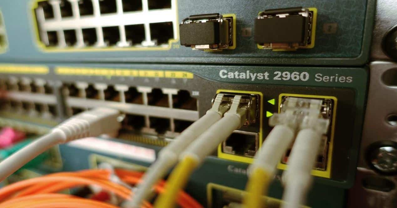
A router has multiple ports, each of which, in turn, is a network interface. When we speak of a network interface, we are referring to a hardware component which allows the device to connect to any network. Consequently, the router has several network interfaces, that is, several network cards packed into one device.
In some ways, it is similar to a computer. Although all computers have one wired network interface, you can add one or more network cards so that your computer has multiple interfaces, according to our needs. The same goes for wireless network interfaces, meaning that you can have multiple wireless network interfaces on one computer. The latter is especially useful if you are interested in activities related to hacking Wi-Fi networks.
Router on a stick
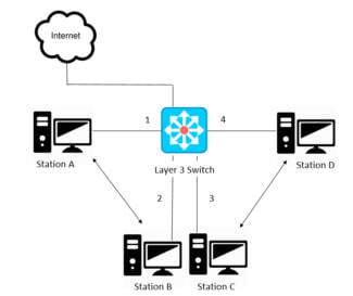
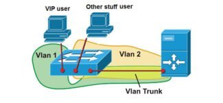
If your network has more than one VLAN, the switch cannot perform the function of allowing a computer in VLAN 1 to communicate with VLAN 2, unless it is an L2+ or L3 switch that includes Inter functionality. -VLAN routing, in which case you can.
If you have a "normal" L2 switch, you will need router services to interconnect VLANs, decapsulate and encapsulate VLANs for proper communication. What does Router-on-a-Stick mean? Let's look at this example network:
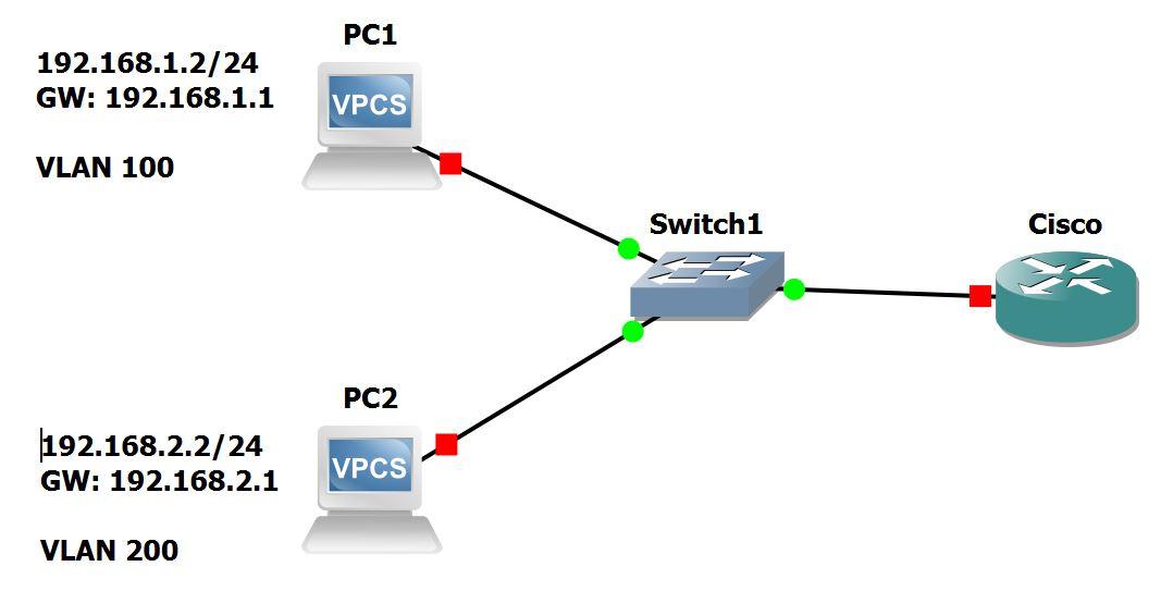
Two computers are presented, each connected to a VLAN. One to VLAN 10 and the other to VLAN 20. These computers are connected to the switch through their respective interfaces. That is, the switch has two ports occupied by both computers. On the other side of the switch, there is a connection between it and the router. On a strictly physical level, if you have two VLANs, you can select one router port for each port to connect to the switch. So in this case, too, the switch must have two trunk ports.
If we scale the case to four, five, six or more VLANs, it will be almost impossible. It is very easy for both the router and the switch ports to be busy, which causes various difficulties in managing both devices. This is why the Router-on-a-Stick concept allows us to create sub-interfaces in the router, that is, in the same physical interface of the router we can create virtual interfaces or sub-interfaces, and each of them He will be connected to one of the VLANs that we have in our network.
As for the switch, if we apply Router-on-a-Stick, we only need a trunk port.
How to configure the sub-interfaces
We first noted that sub-interfaces are heavily used in Cisco vendor devices. That's why we're going to demonstrate its work through the configuration through the CLI (command line interface) of the Cisco router itself. The first thing we must ensure is that the switch or switches in our network are properly configured for access ports and VLAN assignments.
Router Functions
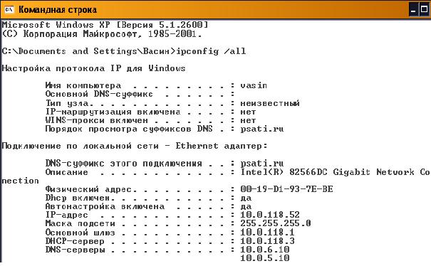
In datagram-based local telecommunications networks, devices need both a MAC address and an IP address, which for each node form a corresponding pair. On each end-node you can see its physical address and IP-address using the ipconfig /all command (Fig. 6.7). The printout shows that the physical MAC address of the end node is 00-19-D1-93-7E-BE and the logical IP address is 10.0.118.52.
The ARP protocol can automatically determine the MAC address of a device from the IP address. Each device on the network maintains a table ARP tabletable that contains the corresponding MAC and IP addresses of other devices in the same local network. The ARP table of any node can be viewed by using the arp -a command (Figure 6.8). The table entries are stored in RAM , where they are dynamically maintained.
If nodes do not transmit data for a long time, the corresponding table entries are deleted, as shown in Fig. 6.8, where the table contains only one pair of IP and MAC addresses.

The ARP table is replenished dynamically by monitoring the traffic of the local network segment. All stations on the local Ethernet network analyze the traffic to determine if the data is intended for them. In doing so, the IP and MAC addresses of the datagram sources are recorded in the ARP table . For example, after communicating with host 10.0.118.65, a second entry appears in the ARP table ( Figure 6.9).

When the device transmits a packet at the destination IP address, it checks whether the ARP table has the corresponding destination MAC address. If the corresponding entry is present, it is used when encapsulating the packet into a data frame. The data is transmitted over the network environment and the destination device receives it.
Brief summary
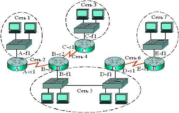
- Combining multiple local networks into a global (distributed, composite) WAN-network takes place using devices and protocols of Layer 3 networking of the seven-layer OSI reference model.
- The most common devices interconnecting networks, subnets and devices are routers.
- Routers have both LAN – and WAN – interfaces and therefore are devices for both local and wide area networks.
- The main functions of routers are to select the best path for packets to reach their destination and to forward a received packet from the input interface to the corresponding output interface.
- The configuration file is stored in NVRAM . It contains commands and parameters for controlling the traffic flow. The configuration file specifies the network protocols and routing protocols that determine the best path for packets to the addressed network.
- The router evaluates the available paths to the destination and chooses the most rational route based on some criterion – metrics.
- The administrator can configure static routes and maintain routing tables manually. However, most routing tables are created and maintained dynamically through the use of routing protocols that allow routers to automatically exchange network topology information with each other.
- A router retransmits a packet by pushing it from an input interface to an output interface, for which it uses the network part of the destination address and refers to the routing table.
- The main parameters of the routing table are the destination network address and the network address of the input interface of the next router on the way to the destination (next hop ) or the router's own output interface.
- Address Resolution Protocol (ARP) implements the process of finding the MAC address from a known network address (IP address). The ARP table contains the MAC and IP addresses of other devices on the same local network.
- The default gateway is the interface through which all packets from the local network will be transmitted to remote networks.
Wireless Router Setup and Configuration
The router will have the port labeled DSL, which is connected using the RJ12 к microfilter, and then to your telephone line. (ADSL and VDSL)
Always remember to use the microfilter, as it may not work or work intermittently without it.
Note: New connection points have a built-in filter.
For fiber and cable, use the WAN port on the router to connect to cable or fiber modem Using an Ethernet cable.
Router Configuration
To change the router's configuration settings, you must log in to the router.
- Using a computer connected with a USB cable.
- Using a computer connected with an Ethernet cable and a web interface.
- Using a computer connected with a Wi-Fi Via a computer connected with an Ethernet cable and web interface. Most common.
Using Wi-Fi and a web interface
Almost all home routers can be configured and managed through a web interface. i.e. web browser.
To do this, you need to connect to the router using Ethernet or Wi-Fi port..
To connect using Wi-Fi you need to know:
BT Home Hub., which I use, comes with a handy pull-out card with the details printed on it, as shown below.
Step 1: Setting up the Wi-Fi
First step – Set up Wi-Fi access on your laptop/PC using your Wi-Fi credentials (SSID and password).
Now you will be able to connect to the router, and the router should assign you IP address.
Placement of the wireless router
There are two things to consider when choosing a location for your home router.
Where you place the wireless router is important, especially if you have a large home.
The router needs mains power as well as access to an Internet connection point.
For the best Wi-Fi coverage, however, it should ideally be placed in the center, not cluttered with large objects, or placed in a closet near electrical appliances with motors.
If your Wi-Fi coverage is poor because of your current location, you need to expand your coverage area.
From a security standpoint, you should try to limit the Wi-Fi signal to your home, so it's not recommended to place it on a windowsill facing the street.
Router features
In local telecommunications networks based on datagrams, devices need both the MAC address and the IP address, which form a corresponding pair for each node. On each end-node you can see its physical address and IP-address using the ipconfig /all command (Fig. 6.7). The printout shows that the physical MAC address of the end node is 00-19-D1-93-7E-BE and the logical IP address is 10.0.118.52.
The ARP protocol can automatically determine the MAC address of a device from the IP address. Each device on the network maintains a table ARP tabletable that contains the corresponding MAC and IP addresses of other devices in the same local network. The ARP table of any node can be viewed by using the arp -a command (Figure 6.8). The table entries are stored in RAM memory, where they are dynamically maintained.

If nodes do not transmit data for a long time, the corresponding table entries are deleted, as shown in Fig. 6.8, where the table contains only one pair of IP and MAC addresses.

The ARP table is populated dynamically by monitoring traffic on the local network segment. All stations on the local Ethernet network analyze the traffic to determine if the data is intended for them. In doing so, the IP and MAC addresses of the datagram sources are recorded in the ARP table . For example, after communicating with host 10.0.118.65, a second entry appears in the ARP table ( Figure 6.9).

When the device transmits a packet at the destination IP address, it checks whether the ARP table has the corresponding destination MAC address. If the corresponding entry is present, it is used when encapsulating the packet into a data frame. The data is transmitted over the network environment and the destination device receives it.
Brief summary
- Interconnecting multiple local networks into a global (distributed, composite) WAN is achieved using devices and protocols of Layer 3 of the seven-layer OSI reference model.
- The most common devices for interconnecting networks, subnets and devices are routers.
- Routers have both LAN – and WAN – interfaces and are therefore devices for both local and wide area networks.
- The main functions of routers are to select the best path for packets to reach their destination and to forward a received packet from the input interface to the corresponding output interface.
- The configuration file is stored in NVRAM . It contains commands and parameters for controlling the traffic flow. The configuration file specifies the network protocols and routing protocols that determine the best path for packets to the addressed network.
- The router evaluates the available paths to the destination and chooses the most rational route based on some criterion – metrics .
- The administrator can configure static routes and maintain routing tables manually. However, most routing tables are created and maintained dynamically through the use of routing protocols which allow routers to automatically exchange network topology information with each other.
- A router retransmits a packet by pushing it from an input interface to an output interface, for which it uses the network part of the destination address and refers to the routing table.
- The main parameters of the routing table are the destination network address and the network address of the input interface of the next router on the way to the destination (next hop) or the router's own output interface.
- Address Resolution Protocol (ARP) implements the process of finding the MAC address from a known network address (IP address). The ARP table contains the MAC and IP addresses of other devices on the same local network.
- The default gateway is the interface through which all packets from the local network will be transmitted to remote networks.
Functions of routers
In local networks of datagram-based telecommunications, devices need both the MAC address and the IP address, which form a corresponding pair for each node. On each end-node you can see its physical address and IP-address using the ipconfig /all command (Fig. 6.7). The printout shows that the physical MAC address of the end node is 00-19-D1-93-7E-BE and the logical IP address is 10.0.118.52.
The ARP protocol can automatically determine the MAC address of a device from the IP address. Each device on the network maintains a table ARP tabletable that contains the corresponding MAC and IP addresses of other devices in the same local network. The ARP table of any node can be viewed by using the arp -a command (Figure 6.8). The table entries are stored in the RAM memory where they are dynamically maintained.

If nodes do not transmit data for a long time, the corresponding entries from the table are deleted, as shown in Fig. 6.8, where the table contains only one pair of IP and MAC addresses.

The ARP table is replenished dynamically by monitoring the traffic of the local network segment. All stations on the local Ethernet network analyze the traffic to determine if the data is intended for them. In doing so, the IP and MAC addresses of the datagram sources are recorded in the ARP table . For example, after communicating with host 10.0.118.65, a second entry appears in the ARP table ( Figure 6.9).

When the device transmits a packet at the destination IP address, it checks whether the ARP table has the corresponding destination MAC address. If the corresponding entry is present, it is used when encapsulating the packet into a data frame. The data is transmitted over the network environment and the destination device receives it.
Brief summary
- Combining multiple local networks into a global (distributed, composite) WAN-network takes place using devices and protocols of Layer 3 networking of the seven-layer OSI reference model.
- The most common devices interconnecting networks, subnets and devices are routers.
- Routers have both LAN – and WAN – interfaces and therefore are devices for both local and wide area networks.
- The main functions of routers are to select the best path for packets to reach their destination and to forward a received packet from the input interface to the corresponding output interface.
- The configuration file is stored in NVRAM . It contains commands and parameters for controlling the traffic flow. The configuration file specifies the network protocols and routing protocols that determine the best path for packets to the addressed network.
- The router evaluates the available paths to the destination and chooses the most rational route based on some criterion – metrics.
- The administrator can configure static routes and maintain routing tables manually. However, most routing tables are created and maintained dynamically through the use of routing protocols that allow routers to automatically exchange network topology information with each other.
- A router retransmits a packet by pushing it from an input interface to an output interface, for which it uses the network part of the destination address and refers to the routing table.
- The main parameters of the routing table are the destination network address and the network address of the input interface of the next router on the way to the destination (next hop ) or the router's own output interface.
- Address Resolution Protocol (ARP) implements the process of finding the MAC address from a known network address (IP address). The ARP table contains the MAC and IP addresses of other devices on the same local network.
- The default gateway is the interface through which all packets from the local network will be transmitted to remote networks.
Router settings interface
As we have already understood, to configure the router, we must engage in a dialogue with it. That is, we give it a command, it hears us, understands and executes. The interface between the router and the user is a standard web browser (IE, Firefox, Opera, etc.). This works in the following way.
We connect the router to the computer via a patch cord or via Wi-Fi and start the web browser. Any router has a network IP address, you type it into the address bar of your browser. For example – 192.168.1.1.
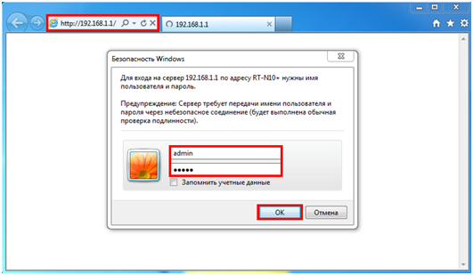
The address of your router is easy to find out – either turn it over and read the IP on the label under the bottom, or in the router's configuration manual.
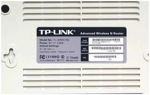
Press "Enter", and the router will immediately ask – and with whom I have the honor to communicate? That is, authorization is required. The user name and password are also listed under the bottom of the router and in the manual. Enter them into the appropriate fields and enter the settings menu.
Router settings
After entering the settings, communication with the router and its configuration starts. For the convenience of a person (but not for a computer or router) settings are made in a convenient menu, with items and sub-items.
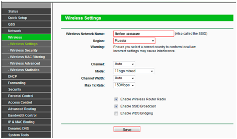
All this "understandability" and "logicality" of the menu only a person needs, and it really works – it is very easy and fast to set up a router, even for a user with little experience. This speaks to the user-friendly interface.
For example, we need to configure Wi-Fi.
Setting up a Wi-Fi router
Of course, we go to the "Wireless" menu item, which means wireless network.
Network Interface
Let's take a look at the second case of the interface, already a physical interface (previously it was dialogical). Although at first glance there is nothing in common between them, but there is common – it is an interface. Only in this case it is a network interface – there is a physical connection of the router to the computer network by wires with special connectors (ports), or by wireless connection, which in this case is not important.

These ports are used to physically connect the computer network wires. They are of at least two kinds – "looking" into the outside world, i.e. connecting to another network or provider (WAN port), and "looking" into your own internal network (LAN ports). The Linux operating system has even named these ports – the WAN port is designated "eth0" and the LAN port "eth1".
Next, we'll look at the two connection interfaces, wired and wireless, and their settings.
Wired interface
A wired connection requires a network wire. There are several types – twisted pair, coaxial cable, and fiber optic.
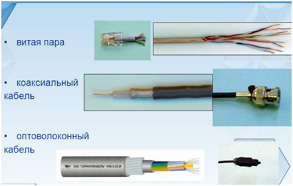
Each type has its own connector, that is, you cannot plug a coaxial cable into a twisted-pair port.
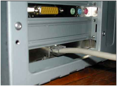
The most commonly used type is twisted pair – the golden mean between price and data transfer speed. The cable is connected to the corresponding port of the router (network interface of the router), and the other end to the network card of the computer (network interface of the PC).
Configuring the WAN and LAN interfaces
With the wires connected, let's move on to configuring the router. We learned about the procedure of entering the settings via the web interface at the beginning of the article. After entering the settings we go to the "Network" tab.
Conclusion
At this point, the introduction to the main characteristics of routers can be considered complete. I hope that this information will help you to choose your own router. Moreover, if necessary, the information given in the "Wired connection interfaces" section will help you to choose a switch, and in the "Wireless connection interfaces" section – to choose an access point.
However, in this material, we have only taken the first step toward understanding such a complex device as a router. The router, even with the most advanced technical characteristics, for successful and productive work requires the correct configuration of many parameters, but we will talk about this already in a separate article.
Applications

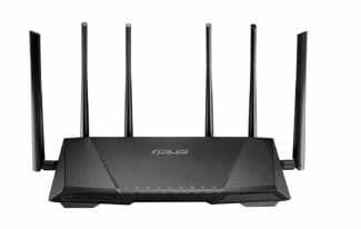
Typical home or small office DSL router showing telephone socket (left, white) connect it to the Internet using ADSL, and Ethernet jacks (right, yellow) to connect to home computers and printers.
The router can have interfaces for different types of physical layer connections, such as copper cable, fiber optic, or wireless transmission box. It can also support different network layer transmission standards. Each network interface is used to forward data packets from one transmission system to another. Routers may also be used to connect two or more logical groups of computer devices, known as subnets, each with its own network prefix.
Routers can provide connectivity within businesses, between businesses and the Internet, or between Internet Service Providers (ISPs). The largest routers (such as the Cisco CRS-1 or the Juniper PTX) connect different ISPs or can be used in large corporate networks. [5] Smaller routers usually provide connectivity to typical home and office networks.
Routers of all sizes can be found within enterprises. [6] The most powerful routers can usually be found at Internet service providers, academic and research institutions. Large businesses may also need more powerful routers to handle the ever-growing demands of intranet data traffic. And the hierarchical interconnection model for connecting routers in large networks is widely used. [7]
Access, Core, and Distribution

History

The first ARPANET router, the Message Interface Processor was delivered to the University of California, Los Angeles on August 30, 1969 and was put into service on October 29, 1969.
Concept The interface computer was first proposed by Donald Davis for the NPL Network in 1966. [17] The same idea was invented by Wesley Clark the following year for use on the ARPANET. Named Interface Message Processors. (IMP), these computers had essentially the same functions as today's routers. The idea of a router (a.k.a. gateways at the time) originally originated with an international group of computer network researchers called the International Network Working Group (INWG). Created in 1972 as an informal group to consider technical issues related to the connection of various networks, it became a subcommittee of the International Federation for Information Processing later that year. [18] These gateway devices differed from most previous packet switching schemes in two ways. First, they connected heterogeneous networks, such as serial lines and LANs. Second, they were connectionless devices that played no role in ensuring reliable traffic delivery, leaving it entirely up to the hosts. This particular idea, the end-to-end principle, had previously been first applied to the CYCLADS network.
The idea was explored in more detail with the intention of prototyping the system as part of two simultaneous programs. One was the first DARPA-initiated program that created the TCP/IP architecture used today. [19] The other was a program at Xerox PARC to explore the new networking technologies that gave the Universal Package PARC system; due to corporate intellectual property issues, it received little attention outside of Xerox for many years. [20] Not long after 1974 began, the first Xerox routers came into service. The first true IP router was developed by Jeannie Strazisar at BBN as part of this DARPA initiative in 1975-1976. [21] By the end of 1976, three PDP-11s were in experimental prototype Internet routers. [22]
External interface.
WAN – the router's external interface, is used to connect to an ISP. Most often the Ethernet interface (or FastEthernet 10/100 Mbps) is used as the WAN port. All parameters related to this section describe the type of connection. There can be several options for the connection type: Dynamic IP (Dynamic IP).Also called "DHCP Client". The router automatically obtains its IP address, default gateway addresses and DNS server addresses. This type of connection is quite widespread and gives the provider sufficient flexibility in configuring his network. In this case, customers may be given both permanent, reserved for clients addresses, and freely selectable from the range of available. Static IP address (Static IP) is most often used by corporate clients who need a permanent IP address. With this type of connection, the client needs to set its own IP address, default gateway address and DNS server address provided by the ISP. PPPoE (Point-to-Point Protocol over Ethernet) This is an authentication method popular with DSL Internet providers. To connect, the user is required to specify a name and password, and authentication, monitoring and control of connections are provided. It is quite convenient for a customer because it requires minimal knowledge when setting up. PPPoE is now supported by almost all routers. PPTP (Point-to-Point Tunnelling Protocol) is generally used to establish a private connection to an ISP over a LAN. It requires a user name and password and a server address to establish a connection. 802.1X – A security standard that provides for user authentication on the network. Typically used in EAP-MD5 mode. Not all routers support this type of connection, so if this is what your ISP uses, you should be especially careful when choosing a router. MTU. The Maximum Transmission Unit parameter is the most interesting for those who use PPPoE connection or for those who are trying to set up a VPN connection or both at the same time. The need to change this parameter is caused by the network settings of some ISPs. You can learn more about what these changes mean at speedguide.net, but we think you should not change this setting unless your ISP or manufacturer advises you to do so.
Security
Blocking WAN ping requests from outside, Stealth mode. Since ping requests are often used to determine the availability of a particular host on the Internet, failing to respond to such a request hides your computer's presence on the network. Many routers allow you to block ping requests or, more precisely, to block responses to these requests, hiding your presence on the network. Content filtering. Content filtering is designed to limit internet users' access to the Internet resources with questionable content. Depending on the version, it allows creating black or white lists of URLs or IP addresses or making use of third-party content filtering lists. It should be noted that content filtering can be applied to all computers in the local network or only to some of them, moreover, it is often possible to schedule the work of these lists. Access Control, Port Filtering In many small organizations, access to Internet services is limited. One option for such restrictions can be the use of a router. So, some users can be allowed access only to e-mail, while others can add access to Web pages and ICQ, and still others can use all services without restrictions. For ease of configuration, routers allow you to create groups of local users, for which you can allow or deny access. In addition, most routers allow activation of scheduled restrictions. Also interesting are the differences in the router's actions when blocking unauthorized traffic. Some simply block, giving the user the impression that the service is unavailable and does not manifest itself in any way, while others transmit the appropriate message to the user and log access attempts in the router's system log. Virtual Private Networking (VPN). Virtual Private Networking is a rather popular topic related to computer network security. Thanks to VPN technologies, it has become possible to use public unsecure networks such as the Internet to transmit data securely, using encryption and digital signing capabilities. With such a connection, the user can work with the resources of the remote network just as with those of the local network. Many router manufacturers have started to release models with VPN support, ranging from simple VPN tunneling, to full-fledged built-in PPTP or IPSec servers. The following protocols are used to create VPNs: IPSec (Internet Protocol Security), PPTP (Point-to-Point Tunneling Protocol), L2TP (Layer 2 Tunneling Protocol), SSL. VPN pass through tunnels (VPN pass through) allows VPN tunnels to pass through the router; having this feature has become a de facto standard, although not all devices could previously have a VPN connection through them. VPN client Allows you to initiate a connection to a VPN server. It is of interest to subscribers of providers that provide network access via VPN (PPTP is often used), as well as for branch offices of enterprises that need a secure connection to the central office. VPN server Allows receiving connections initiated by clients. Often used in corporate headquarters to connect branch offices and employees. Support for VPN tunnels (VPN Endpoint). Creating a virtual tunnel between router networks most often involves the use of IPSec protocols, which allow encryption and decryption of transmitted data, as well as checking their immutability and exchange of keys. This scenario is the most actively used today to connect several remote from each other networks.
Read More:
