Even if you have a good signal, but if there are too many routers on the channel, data packets can be lost, making the signal worse. And with it drops the speed of the Internet, lags, interruptions, increases ping.
- Theory:Wireless Networks:Signal Measurement
- Decibel-milliwatts (dBm, dBm)
- advertisement
- advertisement
- How to improve communications
- Antenna Gain.
- Comparison of experimental results with the model ITU-R 1238
- advertisement
- advertisement
- 1. Power and Sensitivity
- 2. Number and type of obstacles
- Frequency ranges of Wi-Fi networks
- 5 GHz Band
- TX Power signal control on the Asus router
- Setting the wifi signal strength on your Zyxel Keenetic router
Theory:Wireless Networks:Signal Measurement
Wireless networks have many parameters that can be measured. The main ones are:
Decibels is a logarithmic unit of levels, attenuations, and gains. A value expressed in decibels is numerically equal to the decimal logarithm of the dimensionless ratio of a physical quantity to a physical quantity of the same name taken as a reference, multiplied by ten.
In simple terms: In terms of Wi-Fi, Decibels measure how much stronger or weaker a wireless signal has become.
The strength of a radio frequency (RF) signal is usually measured in watts (W). For example, a typical AM radio station broadcasts at 50,000 watts; an FM radio station may broadcast at 16,000 watts. A typical Wi-Fi transmitter typically has up to 0.1 watt (100 mW) of power.
When power is measured in watts or milliwatts, this is considered an absolute measurement. Sometimes it is necessary to compare the power of two different transmitters. For example 1st transmitter (T1) broadcasts with 1 mW, 2nd transmitter (T2) broadcasts with 10 mW, and 3rd transmitter (T3) broadcasts with 100 mW.

So: T2 is 9 mW greater than T1 and 10 times greater, while T3 is 90 mW greater than T2 and 10 times greater.
A more interesting picture will occur if we try to compare the 4th transmitter (T4), which broadcasts with 0.00001 mW, and the 5th transmitter (T5), which broadcasts with 10 mW.

Total: T5 is greater than T1 by 9.99999 mW and at the same time 1.000.000 times more powerful.
So which way to use? Comparison of absolute values in mW or comparison of relative values in "raz"?
Decibel-milliwatts (dBm, dBm)
The decibel-milliwatt indicates how many times the power being measured is greater or less than 1 milliwatt. In the case of decibel-milliwatts, the reference point is 1 mW, which is equal to a signal level of 0 dBm. In the Wi-Fi context, decibel-milliwatts measure the signal power that a wireless device sends or receives.
In real life, a transmitter can give out a signal with a power (Tx) 100 mW, but a receiver can still receive (Rx) 0,000031623. Using the above formula we can calculate the following: dB = 10 * log10(0.000031623 mW / 100 mW) = -65 dB. That is, we have obtained that as the signal travels from transmitter to receiver it has changed by -65 dB.
In decibels we calculate the ratio of signal powers, and in decibel-miliwatts the ratio of the signal and one milliwatt. In this way it is more convenient for us to compare each absolute value with some reference point. If the signal power is less than 1 mW, its level is negative. For example, the sensitivity of an 802.11b wireless NIC at 2 Mbps may be -90 dBm. Note that dBm can be added along the way: dBm transmitter power + dBm network loss = received signal in dBm.
advertisement
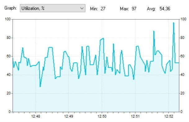
Typical signal strength of a problematic network is -80dBm
However, at variable intervals, usually every few seconds, the signal power of this network, increases sharply at client side (which is my laptop). Namely, the signal power grows to -22dBm (!). Of course, in this case the laptop is in the same place.

Signal power of the TOTOLINK_XXX network.
advertisement
And such a strong signal lasts for quite a long time, acting as an excellent "jammer" of neighboring networks in the frequency bands 1-6, because the owner of the ill-fated network "stretched" its width by 40 MHz.
But the communication problems in neighboring networks are not the worst of it. I'm just afraid to imagine what peak power of radiation this network's home (!) router (probably malfunctioning) produces, instead of the standard 100 mW (20dBm). Further I will try to explain you why it is dangerous and why you should not live near such routers.
A lyrical digression. I have always considered Wi-Fi to be a completely harmless feature. Until I got a laptop Acer Nitro AN515-55 (you can read about it here) with an excellent Intel AX201 wireless adapter. So, I noticed that when I was giving out torrents via Wi-Fi from this laptop, I started to get a headache. I even did a series of confirming experiments to be sure of this unequivocally, rather than write it off to chance. The reason for this is clear – if in the normal operation mode of the laptop wireless adapter mainly works as a receiver, then during the distribution of torrents via ah network (Wi-Fi 6) the laptop turns into a powerful radio transmitter with very heavy traffic. Moreover, in a transmitter located right in front of your face. Even reducing the transmit power to medium had no positive effect. And this despite the fact that the torrent traffic on every home computer, including this laptop, has strict limitations, so as not to "clog" the narrow external 100 Mbit channel to the ISP. This is how I empirically realized that Wi-Fi is not so harmless. In general, now my laptop gives out torrents only when I'm not sitting at it.
Contrary to popular belief, the government is no fool. And the government's radiation power standards for routers are not set in vain.
Lyrical digression 2. Why high-powered routers at home are unnecessary and useless is detailed here.
How to improve communications
Here you have done the test and looked at the strength and power of the wi-fi signal. Now comes the question of how to improve your connection. Here are a few tips:
- To improve quality, try to put your router in an open area. Also the signal strength of the router drops when exposed to radio waves from microwaves, radios, phones.
- I've already said about channels – try setting a free channel in the router's settings.
- There are devices that can improve the quality of reception. They are also called repeaters or repeaters. They catch the signal from the main unit and simply repeat it in their area. A great way to expand the area in your suburban home.
- You can buy more powerful antennas and set the signal strength in the router settings to maximum. True, not all transmitter firmware allows you to do this. So you just need to go to the Web-interface and see if this option is there.
- Buy a more powerful router.
Antenna Gain.
The AMC is not measured in power, since it cannot consume electricity, but it does use dBi as a parameter. But, oddly enough, the CG can be increased, by reducing the radius of coverage of a single beam. Let me give you an example of a light bulb. If we turn on a light bulb, it will scatter light in all directions.
Now we take the bulb and screw it into a flashlight, which begins to reflect the beam to one side due to the walls. If we narrow the exit hole, the beam will strike farther, but the radius of the circle of the light itself will be smaller. And if we make the hole even smaller, we get a laser that can beat even farther.
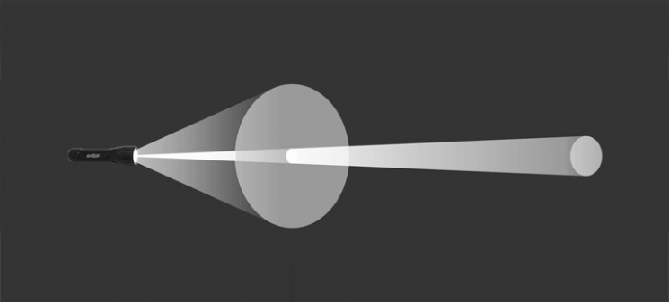
The power of the whole transmitter, in our case the router, will be the sum of the power (dBm) and the antenna gain (dBi). As a result we will get dBm. For example, to improve the signal in expensive routers several antennas are used. Each such antenna has an increased gain. But as you already know, it decreases the range of coverage. That is why you must install more than one such antenna.
- Omnidirectional antennas – are installed on all cheap routers and have a full range of 360 degrees;
- Sector – such antennas have a beam of radio waves with an angle from 60 to 120 degrees;
- Narrowly directional – the angle of 3 to 8 degrees.
Most often narrow beam antennas are used to build a wi-fi bridge for a few kilometers. In this case, there should be almost no obstacles in the way, and the two antennas should be clearly directed at each other.
Comparison of experimental results with the model ITU-R 1238
Problem statement: installed Wi-Fi access point operates in the frequency range of 5 GHz. The receiving device (laptop) is installed in six points, the schematic location of which is shown in Figure 2, and registers the radiated power. The choice of measurement points is made so as to minimize the effect of multipath propagation on the level of the received signal. It is assumed that the maximums of the directional diagrams of the receiving and transmitting antennas are directed at each other.
Before starting the calculation, it should be noted that the authors of the model ITU-R 1238 have made it very flexible, in particular due to the fact that the input coefficient N can vary within a wide range: from 20 to 40 dB. To understand what value to equate N for a particular situation, it is better to refer directly to the original source of the recommendation.
For the range in question, the signal power loss coefficient when passing through walls for our type of problem is Lfn is calculated by the formula Lfn=15=4(n-1).Thus, for points 1-3 Lf(n)=15. For points 4-6 Lf(n)=19 (table 3 of ITU-R recommendation R. 1238-5). The coefficient N used for indoor transmission losses calculation is assumed to be 30 (Table 2 of ITU-R R. 1238-5). Taking into account the chosen geometry of the problem, fading will not be taken into account.
The results of calculations in 6 points according to ITU-R formula are summarized in Table 1, and the distances to each measurement point from the Wi-Fi router are shown in Figure 3.
Figure 3 – Distances from access point to measurement point
advertisement
That said, wireless routers/TDs always have a CCA Threshold – a signal audibility threshold, and if the signal level does not exceed this threshold, the router/TD considers it noise. Suppose this threshold is 82 dBm. Thus, our conditional router with 5 dBi antennas will work with devices, the signal level from which at the location of the router is at least -87 dBm (-87 dBm signal + 5 dBi gain router antenna = -82 dBm).
Note: Of course, this is just a tentative example with all parameters conditionally-typical and given to understand the situation; your router may have antennas with the gain different from 5 dBi, and different threshold, for example – for some Ubiquiti equipment in general stable connection is guaranteed at -70dBm signal level; threshold for 5GHz networks is lower than for 2,4GHz even on the same equipment, etc., but these are nuances, we will not go into details.
In general for the router and the client we can be guided by a simple rule: all other things being equal, the signal loses 6 dB of power (i.e. 4 times as much) when the distance from the transmitter is increased by a factor of 2.
However, as mentioned above, the signal strength of the router/TD is usually 2-8 times higher than on the clients. And with the distance from the router/TD inevitably there will be a situation where the client will hear the signal of the router well, but the router will hear a weaker client signal at the "edge" of possibilities or not hear at all (because the client signal level will fall below the CCA Threshold of audibility). And there will be a strange situation when the Wi-Fi signal from the router on the client device seems to be caught, but there is no connection or it constantly "fails".
advertisement
The reason is the asymmetry in the "strength" of the connection: for example, when a 14 dBm client hears the router/TD at -84 dBm (-84 dBm + 2 dBi client antenna gain = conditional hearing threshold -82 dBm), the signal from the client reaches the router/TD only at -90 dBm, which is below the hearing threshold. Under these conditions, the wireless connection is guaranteed to break down.
That is, in wireless communication channels already at the typical standard parameters of the routers / TDs there is a significant problem with the connection, caused by the asymmetry of the power of Wi-Fi emitters. And if you additionally increase the signal power on one side (router/TC), the problem will only worsen. Moving with mobile clients, you will increasingly often encounter a situation where a Wi-Fi router "loses" devices, and that's because it has a significantly stronger signal. The client will "hear" the router/TD, but the client's router will not. This is why serious equipment manufacturers do not recommend using Wi-Fi routers and access points at maximum power. To prove this, here is a fragment of a Cisco presentation (you can read the full presentation here).
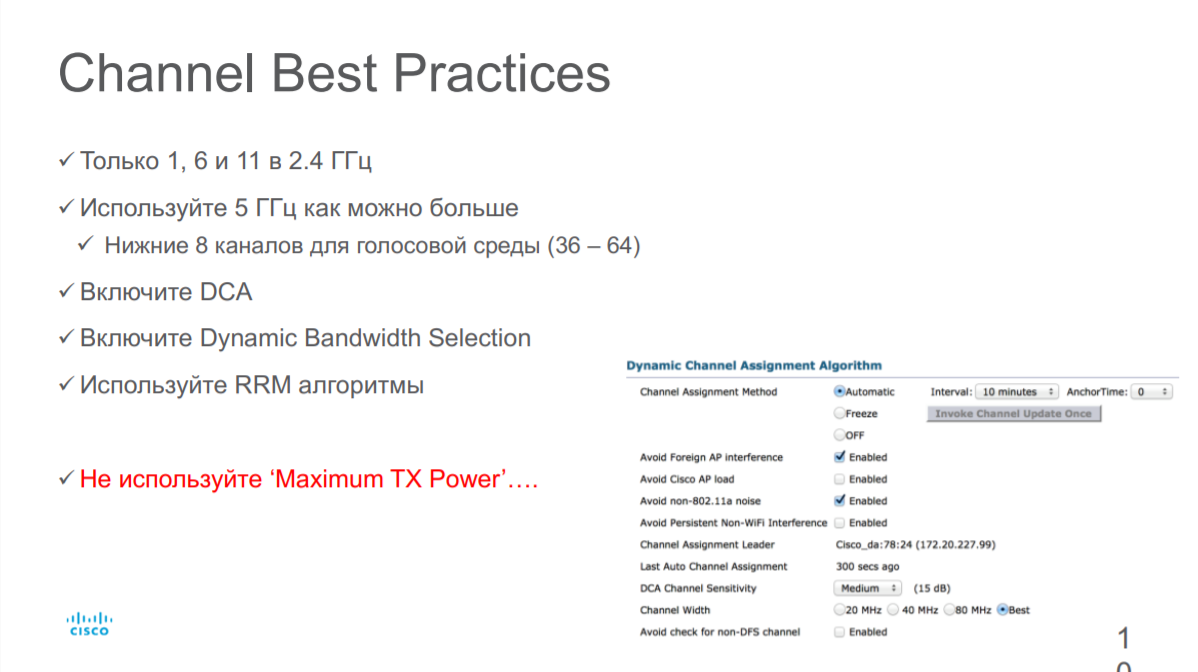
Even on the contrary, to eliminate asymmetry and obtain a stable connection, it is recommended to reduce the Wi-Fi transmitter power in the router/access point.
But if not signal strength, then what determines the speed and reliability of a Wi-Fi connection?
The connection speed, which doesn't tell you anything.
Three parameters determine Wi-Fi connection speed: modulation type, number of streams (depends on the number of antennas) and radio channel width.
But the "theoretical" connection speed based on the above parameters has little to do with the actual speed of the wireless network. What affects this speed?
The fact is that modulation in the network is not constant. The most advanced modulations today are 256 QAM and 1024 QAM (the modulation determines how many bits are transmitted in one radio symbol). But! These dense modulations are very sensitive to noise. And they are only achieved at high signal-to-noise ratio (SNR) when the client is close to the Wi-Fi router/TD. With the distance from the router/TD increases noise, SNR drops, modulation is simplified for reliable connection and, as a consequence, the communication speed drops. Plus, interference adds to the problems of the network.
1. Power and Sensitivity
Transmitter power authorized by IEEE 802.11 for Wi-Fi wireless equipment must not exceed 20 dBm, which is equivalent to 100 milliwatts. Actual equipment averages between 15 and 18 dBm. It mostly has to do with the unwillingness of the manufacturer to take the risk since a device with more than 20 dBm just won't pass the certification.
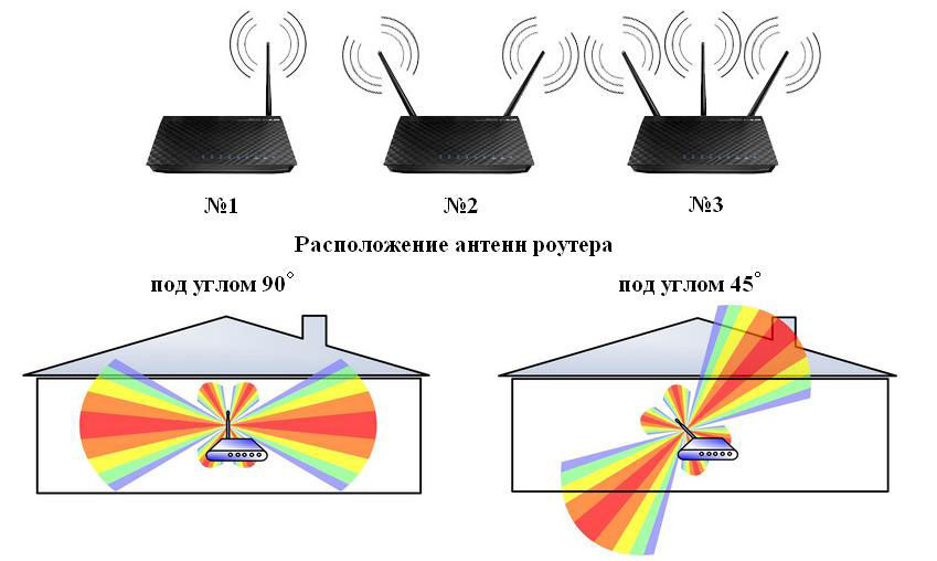
There are two things to pay attention to: firstly, you need to understand what part and in which direction the Wi-Fi adapter, or rather its antenna, radiates. The vast majority of home-versions of access points have omni-antenna with a circular radiation pattern in the form of a torus (in first approximation), Figure 1.
Figure 1 – Appearance and Directivity Diagram of Omni-Antenna
The torus has a radiation pattern in the angular plane in the shape of a figure of eight, and in the azimuthal plane in the shape of a circle. To ensure the most favorable reception conditions of the network user should be located in the direction of the maximum radiation. Given that the antenna in question is omni-directional, it simply must be placed parallel to the receiver (receiver antenna). This condition is illustrated by figure 2.
Figure 2 – Illustration of the dependence of the reception quality on the relative orientation of the transmitter and receiver
Thus if the location of your laptop corresponds to the direction of "minimal radiation" (Fig. 2) you should not be surprised with the low quality of reception. Considering that the antennas, coming with the router, have a "rotation system" in the base, then what options of orientation you will not meet in the apartments of everyday people.
2. Number and type of obstacles
The motto of the section: use logic when placing equipment.
Of course, it is quite difficult without special equipment to consider the number of obstacles and their type in the way of radio signal propagation, but there are a few rules, following which you can "save" a couple of decibels of power.
The average length of a Wi-Fi wave in the 2.4 GHz band is 12.5 centimeters and 6 centimeters for the 5 GHz band, so for large objects (walls, floors, cabinets, doors, etc.) you can use the principle of geometric optics, assuming that the signal propagates in a straight line (partially reflecting and refracting). This is, of course, a rough assumption, but at any rate it will allow you to "eyeball" the direction of signal propagation and clear (if possible) its path.
The first thing to keep in mind is that the signal passes very poorly through metalized surfaces and respectively reinforced concrete slabs. Upon reaching a metal object, the electromagnetic wave continues to propagate along its surface, dissipating. Therefore, ideally, the access point should be placed away from safe doors, iron tables and so on. If it is necessary to ensure that the signal passes through a thick wall (the type of material is not important), you should try to ensure that the path from the source to the receiver through this obstacle is minimal. This condition is demonstrated by the illustration in Figure 3.
Figure 3 – Illustration of the signal power level after passing through an obstacle
Frequency ranges of Wi-Fi networks
Most conventional client routers and consumer Wi-Fi devices operate in two frequency bands: 2.4 GHz (802.11 b/g/n) and 5 GHz (802.11 a/n/ac).
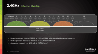
There are 14 channels defined by standards in the 2.4 GHz band. Some of them may not be available in some countries (for example, channel 14 is only allowed in Japan). Channels with numbers 1, 6 and 11 are considered to be completely non-intersecting in frequency and are called, oddly enough, "non-intersecting". But in fact, there is always an "unaccounted for" and if the access points are close enough to each other, then the non-intersecting channels become intersecting as well:
Each channel occupies a width of 20 MHz. In some cases, standards allow a channel width of 40 MHz (see Channel Aggregation section). Channel numbers and their center frequencies are shown in the figure.
Use of non-intersecting channels is convenient in the case when it is necessary to organize uniform radio coverage so that nearby equipment does not interfere with each other, thereby increasing stability and quality of communication:
One of the disadvantages of the 2.4 GHz band is its high congestion and small number of channels. Not only other Wi-Fi devices and access points, but also Bluetooth devices operating in the same frequency range can interfere with the Wi-Fi network. Even an ordinary household microwave oven can have a very large impact on the quality of the connection in the 2.4 GHz band. To minimize the mutual influence, the power of Wi-Fi transmitters is strictly limited and regulated. The use of a high-power transmitter requires a permit from the radio frequency center.
5 GHz Band
There are 23 non-overlapping 20 MHz channels available in the 5 GHz frequency band. It can even be noted that the 5 GHz band only consists of non-overlapping channels, as overlapping creates significant collisions at this frequency. Here you can already use not only the 20/40 MHz band, but also the 80 MHz wide channels (main + auxiliary). The following shows the arrangement of the channels in the 5 GHz band:
- The first block (Lower) of UNII-1 channels lies in the frequency range from 5180 to 5240. At the same time, the available non-overlapping 20 MHz channels are: 36, 40, 44, 48;
- The second block (Middle, middle) UNII-2 lies in the frequency range from 5260 to 5320. The available non-intersecting 20 MHz channels, however, are: 52 56 60 64;
- The third block (Extended) of UNII-2 lies in the frequency range from 5500 to 5700. The available non-intersecting 20 MHz channels are: 100 104 108 112 116 120 124 128 132 136 140;
- The fourth UNII-3 block is from 5745 to 5805, with available non-intersecting channels at 20 MHz: 149 153 157 161;
- Separately, there are 3 groups of channels: Japan (channels: 8, 12, 16; range 5040-5080) US Public Safety (channels: 184, 188, 192, 196; range 4920-4980) ISM (channel 165, frequency 5825);
- The 802.11ac standard provides for UNII-1, UNII-2 (both) and UNII-3 groups, i.e. a total of 23 channels. This makes 5 non-overlapping channels available when using the 80 MHz channel width. The same specification provides the ability to combine 2 channels at 80 MHz, resulting in a total of 160 MHz.
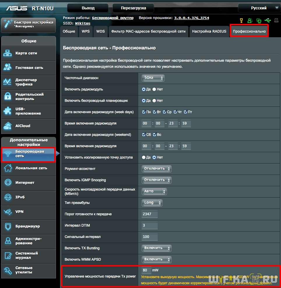
TX Power signal control on the Asus router
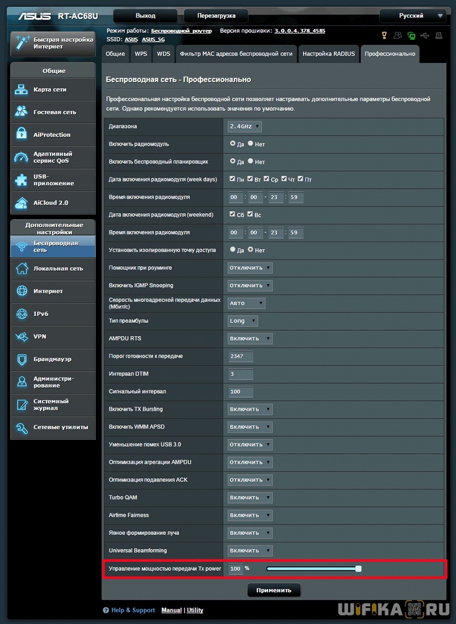
On the Asus router, the output power settings are in the "Wireless Network" section, in the "Professional" tab, but are not available on all models. Here, if you scroll to the bottom of the page, you'll see the last item, "TX Power Signal Control." In some Asus routers, the wifi power must be prescribed independently in numbers in video units of mW – a maximum of 200mW.
In others, this is done more clearly as a slider in percentage of maximum signal strength
Setting the wifi signal strength on your Zyxel Keenetic router
In order to increase or decrease the wifi power on the router Zyxel Keenetic, you need to go to the menu "Wi-Fi Network" and among all other settings find the line "Signal Power". Here from the drop-down list select the required value in %.

If you own a more advanced Keenetic router, to adjust the TX Power, open the "Home Network" menu and then click on the "Advanced Settings" link.
Read More:
