You will learn how dBm is used to indicate wifi power level and wifi signal strength. In most cases, this is just for your information. There is little you can do with signals other than move your device or broadcast wifi network around.
- Theory:Wireless Networks:Signal Measurement
- Decibel-milliwatts (dBm, dBm)
- dBm – Wi-Fi signal strength as a function of power
- What is dB
- When you can (and should) change dBm
- Choosing the right dBm value
- What does WiFi signal strength depend on
- How to check the level
- To check your Wi-Fi signal strength using Windows
- "Wi Fi detector" from your phone
- Signal strength in PC apps
- advertisement
- advertisement
- Phone apps
- How to improve the connection
- advertisement
- advertisement
- 2. The number and type of obstacles
- Interference of radio waves
- Models for calculating Wi-Fi signal loss
- Comparison of experimental results with model ITU-R 1238
- Relationship of WiFi signal frequency and wavelength
- Properties of a WiFi signal
- Antenna Gain
- Antenna Angle, Beamwidth, degree
Theory:Wireless Networks:Signal Measurement
Wireless networks have many parameters that can be measured. The main ones are:
Decibels is a logarithmic unit of levels, attenuations, and gains. A value expressed in decibels is numerically equal to the decimal logarithm of the dimensionless ratio of a physical quantity to a physical quantity of the same name taken as a reference, multiplied by ten.
In simple terms: In terms of Wi-Fi, Decibels measure how much stronger or weaker a wireless signal has become.
The strength of a radio frequency (RF) signal is usually measured in watts (W). For example, a typical AM radio station broadcasts at 50,000 watts; an FM radio station may broadcast at 16,000 watts. A typical Wi-Fi transmitter typically has up to 0.1 watt (100 mW) of power.
When power is measured in watts or milliwatts, this is considered an absolute measurement. Sometimes it is necessary to compare the power of two different transmitters. For example 1st transmitter (T1) broadcasts with 1 mW, 2nd transmitter (T2) broadcasts with 10 mW, and 3rd transmitter (T3) broadcasts with 100 mW.

So: T2 is 9 mW greater than T1 and 10 times greater, while T3 is 90 mW greater than T2 and 10 times greater.
A more interesting picture will emerge if we try to compare the 4th transmitter (T4), which broadcasts with 0.00001 mW, and the 5th transmitter (T5), which broadcasts with 10 mW.

Total: T5 is greater than T1 by 9.99999 mW and at the same time 1.000.000 times more powerful.
So which way to use? Comparison of absolute values in mW or comparison of relative values in "raz"?
Decibel-milliwatts (dBm, dBm)
The decibel-milliwatt indicates how many times the power being measured is greater or less than 1 milliwatt. In the case of decibel-milliwatts, the reference point is 1 mW, which is equal to a signal level of 0 dBm. In the Wi-Fi context, decibel-milliwatts measure the signal power that a wireless device sends or receives.
In real life, a transmitter can give out a signal with a power (Tx) 100 mW, but a receiver can still receive (Rx) 0,000031623. Using the above formula we can calculate the following: dB = 10 * log10(0.000031623 mW / 100 mW) = -65 dB. That is, we have obtained that as the signal travels from transmitter to receiver it has changed by -65 dB.
In decibels we calculate the ratio of signal powers, and in decibel-miliwatts the ratio of the signal and one milliwatt. In this way it is more convenient for us to compare each absolute value with some reference point. If the signal power is less than 1 mW, its level is negative. For example, the sensitivity of an 802.11b wireless NIC at 2 Mbps may be -90 dBm. Note that dBm can be added along the way: dBm transmitter power + dBm network loss = dBm signal received.
dBm – Wi-Fi signal strength as a function of power
In Wi-Fi networks, dBm is used to refer to two things: The power level of the broadcaster и signal strength at the receiving end.
But, what is dBm? This is where things get interesting (or boring, depending on how deep you want to go into the subject) – first we need to understand what dB is
A little warning.: the next part may be a bit technical.
What is dB
dB is short for decibelwhich is one tenth of a white (B) and is the unit of measurement commonly used for estimation:
- Loudness of sound.. Shows the ratio between the current sound and the lowest sound level perceivable by the human ear, which is 0 dB. In terms of loudness, 60-70 dB is normal conversation, and 125 dB is when you start to feel pain in your ears.
- The difference (or ratio) between the two levels of electrical power.
- The increase or decrease in signal power.
dB is useful because it allows you to calculate signal (power) gain and loss, which can include large scales, by adding or subtracting whole numbers instead of decimals or a complicated formula for recording.
dB – is also a form of scientific notation of power and signal levels of electronic devices. It allows very large numbers to be transmitted in a few symbols.
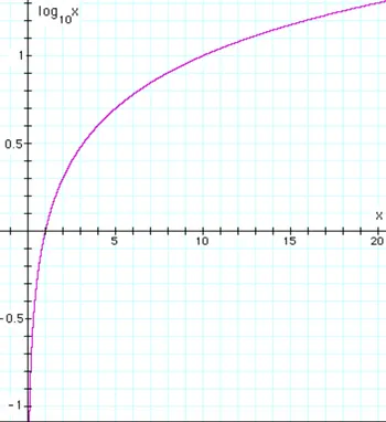
As a general rule, 1,000,000 can be converted to 60 dB, and similarly 0.000001 equals -60 dB. This is because, in logarithmic terms, 6 is the logarithm of 1,000,000, which can be written as 10 6 .
What is most important to remember about dB is that it is not linear, but logarithmic. A higher value in dB always means "more," but that value does not grow evenly. In other words, the "gain" from 1 dB to 2 dB is different from the growth from 5 dB to 6 dB.
When you can (and should) change dBm
Normally you cannot manually change the dBm value. This is because your Wi-Fi client gets at a certain distance from the broadcaster, which is what it is. To change it, you need to physically move the device..
However, with multiple broadcasters, i.e. a mesh Wi-Fi system, changing the dBm value can help the devices move around seamlessly.
In this case, you change the dBm values of the triggers. In other words, you enter a target dBm number at which something will happen.
In particular, if you have multiple broadcasters in your house and you want your Wi-Fi device, such as your phone, to automatically connect to the nearest host rather than a remote one, setting dBm triggers on the broadcasters may help.
By the way, this is called seamless transmission, which is always a tricky business.
Choosing the right dBm value
Not all mesh systems allow you to change the dBm triggers — at best, you can only turn the seamless service on or off.
One system I know of gives you this capability – Asus's AiMeshand I'll use it as an example.
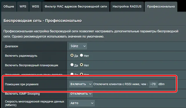
In this case you can adjust the dBm value for the helper on roaming for each frequency band (2.4 GHz, 5 GHz or 6 GHz). And even then it is a bit finicky. This is because, depending on the environment, the router chooses the dBm value that is best for seamless service.
Consequently, you may find that this number differs from one router to another or from one location to another. However, you can use the default value as a baseline.
Speaking of the default value, the number you are likely to see is -70 dBm, the threshold at which the signal strength is still about 60%.
What does WiFi signal strength depend on
The basic characteristics of a wireless network are: range, data rate and connection quality. They are influenced by a lot of factors. Some of them are in the router itself and some are in the external environment:
- 802.11 protocol type – B/G/N/AC;
- Transmitter power;
- The antennas and the number of antennas;
- The length of the wires that are connected to the antenna;
- location of the router;
- the materials of the surfaces and walls;
- obstacles in the apartment (furniture, appliances, mirrors);
- interference from other devices, routers behind the walls, etc.
The most effective standard is considered to be 802.11n. Its coverage area is up to 150 meters in the open and 50 meters indoors. A WiFi signal is transmitted via radio waves. It is a reliable means of communication, but sometimes interference is very unexpected. For example, a WiFi signal strength check shows that WiFi radio waves can be attenuated by obstacles such as tree foliage. This is because leaves and branches contain water, and water shields signals. Therefore, rain and fog also attenuate WiFi (but less so than dense foliage). Brick and metal surfaces have the same effect. Also 802.11b and 802.11g waves are noticeably affected by microwave interference.
Regarding the other metrics, it's not always that simple. For example, in some cases, you can improve the quality of your connection by lowering the transmitter power. To know what the problem is with your connection, it is worth measuring the WiFi signal. Both special detectors and applications installed on devices are used for this purpose. Checking the WiFi signal online is unnecessary, because you need to monitor everything directly "on the ground" near the router. Once you understand whether the network is working properly, you can check the Internet speed.
How to check the level
I will give you some ways to check the WiFi signal quality and the Internet speed. To begin with, there are simple ways to check with Windows, then there are specialized programs and an online Wi-Fi signal check.
To check your Wi-Fi signal strength using Windows
WiFi signal settings are available in their simplest form in the system tray next to the clock. There you can easily see the level as a number of "dashes". It shows the strength of the radio waves your computer is receiving at the moment. However, few people know that you can find out this level more accurately: as a percentage. To do this, you don't need to install any new programs, just follow these steps:
- Right-click on "cmd" from the search results and select "Run as administrator."
- A command prompt will open.
- Enter the line "netsh wlan show" if you have Windows 10, or "netsh wlan show all" if you have Windows 7, and press Enter.
- This will show you information about all the networks that your computer is "catching". The SSID is the name of the network, and among the other parameters there is a percentage indicator – the level of Wi Fi signal. There is also an indicator of channel utilization.
"Wi Fi detector" from your phone
To turn your smartphone into a network scanning device, all you have to do is download a special app.
- Log in to Google Play Store.
- Download and install one of the applications, such as WiFi Analyzer.
- Launch the application. You will see a list of networks, their signal strength and technical information, such as which channels they use.
Signal strength in PC apps
PC applications with WiFi signal strength checks are very powerful. For example, some allow you to build a so-called "heat map" of your WiFi coverage. You can clearly see how the WiFi behaves. For example, this is possible in the free program Ekahau HeatMapper. You "draw" a plan of the building and move around with the computer, fixing the level of connection at different points.
advertisement
Typical signal strength of the problematic network -80dBm
However, at variable intervals, usually a few seconds, the signal strength of this network, increases sharply on the client side (which is my laptop). Namely, the signal power grows to -22dBm (!). Of course, with the laptop in the same place.

TOTOLINK_XXX network signal strength jump
advertisement
And such a strong signal holds for quite a long time, acting as an excellent "jamming" neighboring networks in the frequency bands 1-6, because the owner of the unfortunate network "stretched" its width to 40 MHz.
But the communication problems in neighboring networks are not the worst of it. I'm just afraid to imagine what peak power of radiation this network's home (!) router (probably malfunctioning) produces, instead of the standard 100 mW (20dBm). Further I will try to explain you why it is dangerous and why you should not live near such routers.
A lyrical digression. I have always considered Wi-Fi to be a completely harmless feature. Until I got a laptop Acer Nitro AN515-55 (you can read about it here) with an excellent Intel AX201 wireless adapter. So, I noticed that when I was sharing torrents via Wi-Fi from this laptop, I got a headache. I even did a series of confirming experiments to be sure of this unequivocally, rather than write it off as a coincidence. The reason for this is clear – if in usual laptop's mode the wireless adapter mainly works as a receiver, then during the distribution of torrents via ah network (Wi-Fi 6) the laptop turns into a powerful radio transmitter with a very heavy traffic. Moreover, in a transmitter located right in front of your face. Even reducing the transmit power to medium had no positive effect. And this despite the fact that the torrent traffic on every home computer, including this laptop, has strict limitations, so as not to "clog" the narrow external 100 Mbit channel to the ISP. This is how I empirically realized that Wi-Fi is not so harmless. In general, now my laptop gives out torrents only when I am not sitting at it.
Contrary to popular belief, the government is far from stupid. And the government does not set the radiation power standards for routers in vain.
Lyrical digression 2. Why high-powered routers at home are unnecessary and useless is detailed here.
Phone apps
You can download programs for the Android system at this link.
You have downloaded the program, scanned the wireless network and you see in front of you some numbers and letters. We are interested in the following line RSSI (for inSSIDer). If you are using another program, this field must have a minus sign. There you will see the signal level in dBm or in Russian – power decibels.
Nothing difficult to determine – the lower the number, the better the signal. As you can see I have a signal level of -48. I am in another room and I am separated from the router by one wall, so the signal level could be even better. Once again, -20 dBm is better than -70 dBm, for example.
If the power level is higher than 90, you should think about improving the signal. But you should also look at the channel number in the Channel field. The thing is that most home use is the 2.4 GHz frequency which has 13 channels.
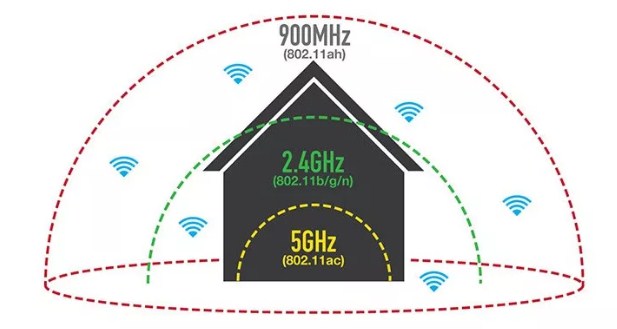
Even if you will have a good signal, but if there are too many routers sitting on the channel, data packets can disappear, get lost, making the signal worse. And with it drops the speed of the Internet, begins lags, interruptions, increases ping.
So, a tip – if you see that your channel is sitting on someone else, then try to restart the router, so it chooses the best channel. Or set the channel manually – my colleague Botan already wrote about this in this article.
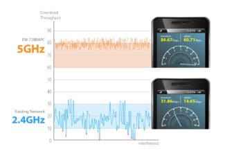
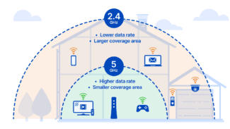
I also want to say a few words about 2.4 GHz and 5 GHz. The 5 has more speed, but the connection is very lame. It's all about technology – the higher the frequency, the smaller the radius of coverage and the faster the wave fades.
How to improve the connection
Here you have done the test, looked at the strength and power of the wi-fi signal. Now comes the question of how to improve your connection. Here are some tips:
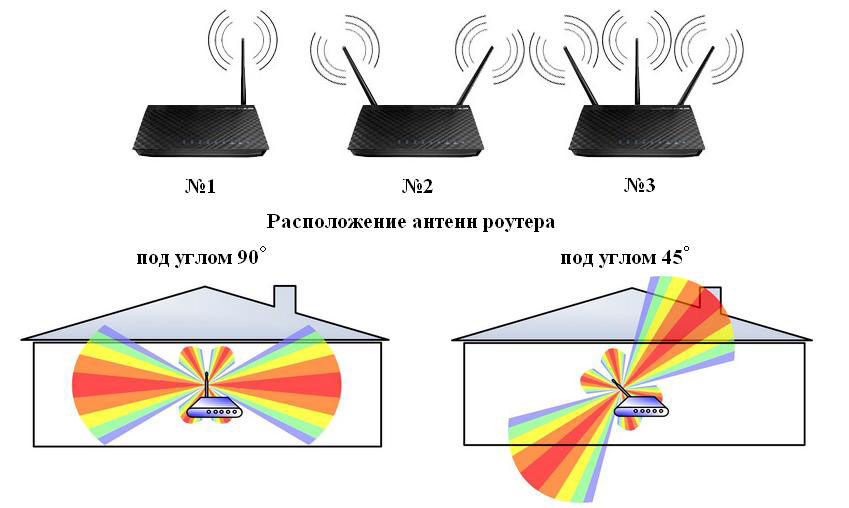
- To improve quality, try to put your router in an open area. Also the signal strength of the router drops when exposed to radio waves from microwaves, radios, phones.
- I've already said about channels – try setting a free channel in the router's settings.
- There are devices that can improve the quality of reception. They are also called repeaters or repeaters. They catch the signal from the main unit and simply repeat it in their area. This is a great way to expand the area in the country house.
- You can buy more powerful antennas and set the signal strength in the router settings to maximum. True, not all transmitter firmware allows you to do this. So you just have to go to the Web interface and see if it's there.
- Buy a more powerful router.
advertisement
That said, wireless routers/TDs always have a CCA Threshold – the signal audibility threshold, and if the signal level does not exceed this threshold, the router/TD considers it noise. Suppose this threshold is 82 dBm. Thus, our conditional router with 5 dBi antennas will work with devices whose signal level at the location of the router is at least -87 dBm (-87 dBm signal + 5 dBi antenna gain router = -82 dBm).
Note: Of course, this is a purely tentative example in which all the parameters are conventionally typical and given to understand the situation; your router may have antennas with a gain different from 5 dBi, and a different threshold, for example – for certain Ubiquiti equipment in general stable connection is guaranteed at signal levels down to -70dBm; threshold for 5GHz networks is lower than for 2.4GHz even on the same equipment, etc., but these are nuances, which we will not go into.
In general for the router and the client can be guided by a simple rule: all other things being equal, the signal loses 6 dB of power (i.e. 4 times as much) when the distance from the transmitter is increased by a factor of 2.
However, as mentioned above, the signal strength of the router/TD is usually 2-8 times higher than that of the clients. And with the distance from the router/TD inevitably there will be a situation where the client will hear the signal of the router well, but the router will hear a weaker signal of the client at the "edge" of possibilities or not hear at all (because the signal level of the client will fall below the hearing threshold of CCA Threshold). And there will be a strange situation when the Wi-Fi signal from the router on the client device seems to be caught, but there is no connection or it constantly "fails".
advertisement
The reason is the asymmetry in the "strength" of the connection: for example, when a 14 dBm client hears the router/TD at -84 dBm (-84 dBm + 2 dBi client antenna gain = conditional hearing threshold -82 dBm), the signal from the client reaches the router/TD only at -90 dBm, which is below the hearing threshold. Under these conditions, the wireless connection is guaranteed to break down.
That is, in wireless communication channels already at the typical standard parameters of the routers / TDs there is a significant problem with the connection, caused by the asymmetry of the power of Wi-Fi emitters. And if you additionally increase the signal power on one side (router/TC), the problem will only worsen. Moving with mobile clients, you will increasingly often encounter a situation where a Wi-Fi router "loses" devices, and that's because it has a significantly stronger signal. The client will "hear" the router/TD, but the client's router will not. This is why serious equipment manufacturers do not recommend using Wi-Fi routers and access points at maximum power. To prove this, here is a fragment of a Cisco presentation (you can read the full presentation here).
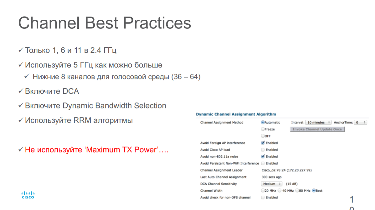
Even on the contrary, to eliminate asymmetry and obtain a stable connection, it is recommended to reduce the Wi-Fi transmitter power in the router/access point.
But if not signal strength, then what determines the speed and reliability of a Wi-Fi connection?
The connection speed, which doesn't tell you anything.
Three parameters determine Wi-Fi connection speed: modulation type, number of streams (depends on the number of antennas) and radio channel width.
But the "theoretical" connection speed based on the above parameters has little to do with the actual speed of the wireless network. What affects this speed?
The fact is that modulation in the network is not constant. The most advanced modulations today are 256 QAM and 1024 QAM (the modulation determines how many bits are transmitted in one radio symbol). But! These dense modulations are very sensitive to noise. And they are only achieved at high signal-to-noise ratio (SNR) when the client is close to the Wi-Fi router/TD. With the distance from the router/TD increases noise, SNR drops, modulation is simplified for reliable connection and, as a consequence, the communication speed drops. Plus, interference adds to the network problems.
2. The number and type of obstacles
The motto of the section: use logic when placing equipment.
Of course, without special equipment it is difficult to take into account the number and type of obstacles in the way of radio signal propagation, but there are a few rules, following which you can "save" a few decibels of power.
The length of the Wi-Fi wave in the 2.4 GHz band is on average 12.5 centimeters and for the 5 GHz band – 6 centimeters, so for large objects (walls, ceilings, cabinets, doors, etc.) you can use the principle of geometric optics, assuming that the signal propagates in a straight line (partially reflecting and refracting). This, of course, is a rough assumption, but in any case, it will allow "by eye" to estimate the direction of signal propagation and to clear (if possible) its path.
The first thing to keep in mind is that the signal passes very poorly through metalized surfaces and respectively reinforced concrete slabs. Once it hits a metal object, the electromagnetic wave continues to propagate along its surface, scattering. Therefore, ideally, the access point should be placed away from safe doors, iron tables and so on. If it is necessary to ensure that the signal passes through a thick wall (the type of material is not important), you should try to ensure that the path from the source to the receiver through this obstacle is minimal. This condition is demonstrated by the illustration in Figure 3.
Figure 3 – Illustration of the signal power level after passing through an obstacle
Interference of radio waves
To determine at home the presence of interference from third-party equipment and, if possible, to reduce its impact, it is recommended to use software analyzers Wi-Fi radio coverage. The article "Software for analyzing Wi-Fi radio coverage – Wi-Fi Site Survey" gives an overview of the capabilities of such programs running on the Windows OS.
In general, the recommendations are as follows. When launching a program, for example, Wi-Fi Scanner (developed by System Lizard), open the diagram of signal level distribution by Wi-Fi frequency channels, Fig. 4. The diagram presents visually the information on wireless equipment surrounding you.
Figure 4 – Appearance of 2.4 GHz band tab, Wi-Fi Scanner program
In the 2.4 GHz band there are 13 frequency channels in the RF. Three of them are conditionally non-overlapping – channels 1, 6 and 11. As practice shows, most of the access points operate on channels 1 and 6. There are also smart access points that can automatically "move" to less noisy channels. The option of auto-tuning the access point is suitable if it is the only one in the network and serves a small number of subscribers. If the access point is part of a large wireless network, this option is categorically unacceptable. Using programs, radio coverage analyzers can simply monitor the channels and select the least noisy. For example, for the situation shown in Figure 4, I would choose channels 11 or 12. Similar reasoning can be applied to the 5 GHz band.
You can never predict all the possible sources of interference; there have been times when a microwave suddenly found itself behind a wall with an access point attached to it, dropping the Wi-Fi network all over dinner.
Models for calculating Wi-Fi signal loss
Radio signal loss models allow you to estimate the attenuation of the electromagnetic wave emitted by a Wi-Fi adapter, taking into account the number and type of obstacles in the path of the signal. This article discusses the signal propagation models used to calculate the signal level inside buildings. The models that will be discussed and their modifications are numerous. In the article the most simple ones are considered, which can be used even in the field without deep mathematical knowledge.
Before the beginning of consideration of various models of spreading of a radio signal we will notice, that in ideal conditions (there are no obstacles on a way of a signal passing and there are no multiple re-reflections of a signal) to estimate signal power in any point of free space (free space – FS) it is possible by the so-called Fris formula:
Figure 1 shows a graph of the dependence of the attenuation LFS with increasing distance for Wi-Fi signal on the first frequency channel (central frequency 2437 MHz) in the range of 2.4 GHz – blue curve, and in the range of 5 GHz – red curve. At the same time, the receiving and transmitting antenna gain coefficients were taken equal to one.
Comparison of experimental results with model ITU-R 1238
Statement of the problem: A Wi-Fi access point has been installed and is operating in the 5 GHz frequency band. The receiving device (laptop) is installed at six points, the schematic location of which is shown in Figure 2, and registers the radiated power. The choice of measurement points is made so as to minimize the effect of multipath propagation on the level of the received signal. It is assumed that the maximums of the directional diagrams of the receiving and transmitting antenna are directed at each other.
Before proceeding to the calculations, it should be noted that the authors of the model ITU-R 1238 made it very flexible, in particular due to the fact that the input coefficient N can vary in a wide range: from 20 to 40 dB. To understand what value to equate N for a particular situation, it is better to refer directly to the original source of the recommendation.
For the range in question the coefficient of signal power loss while passing through walls for our type of problem is Lfn is calculated by the formula LL fn=15=4(n-1).Thus, for points 1-3 Lf(n)=15. For points 4-6 Lf(n)=19 (table 3 of ITU-R recommendation R. 1238-5). The coefficient N used in the calculation of indoor transmission losses is assumed to be 30 (Table 2 of ITU-R R. 1238-5). Taking into account the chosen geometry of the problem, fading will not be taken into account.
The results of the calculations in 6 points according to the formula ITU-R are summarized in Table 1, and the distances to each measuring point from the Wi-Fi router are shown in Figure 3.
Figure 3 – Distances from access point to measurement point
Relationship of WiFi signal frequency and wavelength
Wavelength characteristics are relatively rarely used in the parameters of WiFi equipment. However, sometimes it is a good idea to understand the relationship between frequency and wavelength in order to understand the physical properties and behavior of the wireless signal under different conditions.
A general rule of thumb: The higher the frequency, the shorter the wavelength. And vice versa.
The formula to calculate the wavelength:
WiFi signal wavelength (in meters) = Speed of light (in m/sec) / Frequency of signal (in Hertz).
The speed of light in m/s = 300,000,000.
After simplifying the formula we get: Wavelength in meters = 300 / Frequency in MHz.
Properties of a WiFi signal
Absorption.
The main condition for establishing a wireless link over a distance of more than a hundred meters is direct line of sight between the points where the equipment is installed. To put it simply, if we are standing next to one WiFi access point, we must not look at the other one through a wall, a forest, a high-rise building, a hill, etc. (That's not all, you should also take into account the interference in the Fresnel zone, but about that in another article.)
Such objects simply reflect and absorb the WiFi signal, if not all of it, then the lion's share.
The same thing happens indoors, where the signal from a WiFi router or access point travels through walls to other rooms/floors. Each wall or floor "takes away" some efficiency from the signal.
At a short distance, for example, from the room router to the laptop, the radio signal still has a chance to overcome the wall and still get to the target. But over a long distance of several kilometers, any such weakening significantly affects the quality and range of the WiFi connection.
The percentage of WiFi signal degradation when passing through obstacles depends on several factors:
- Wavelength . In theory, the longer the wavelength (and lower the WiFi frequency), the greater the signal penetration. Accordingly, WiFi in the 2.4 GHz band has a bоhigher penetration than in the 5 GHz band. In the real world, the implementation of this rule depends very closely on what structure and composition of the obstacle the signal passes through.
- The material of the obstacle or more precisely, its dielectric properties.
Non-toned window (no metallic coating)
* The percentage of effective distance – This value means what percentage of the originally calculated range (in open terrain) will be able to pass the signal after overcoming the obstacle.
Antenna Gain
This is another important parameter that affects signal range and bandwidth.
WiFi antenna amplification should not be understood to mean that it will add power to your signal. An antenna is a passive device that does not consume power and cannot "add power" at least according to the law of conservation of energy.
Gain factor (GF) is a relative value that is measured in isotropic decibels (dBi). For a starting point for calculation of this factor (those figures which we see in a column "Gain of the antenna" in technical specifications) the virtual (nonexistent) reference isotropic antenna is taken.
How can the antenna amplify the signal?
Take for example a flashlight with the ability to change the focus of the beam.
A wide beam will illuminate a large area, but not far.
A narrow beam will illuminate a smaller area but "reach" farther.
Antenna gain works in much the same way.
The directional diagram (DN) is a graphical representation of the propagation of the WiFi signal power from the source. The antenna gain is plotted along the radius of the diagram. Since the beam propagates in space both horizontally and vertically, the directional diagrams are made in two planes: horizontal and vertical.
As you see, here the radiation goes in all directions, both in the horizontal and vertical planes. In three-dimensional form, it looks something like this:
Antenna Angle, Beamwidth, degree
Antenna angle or beamwidth – A characteristic that is important for proper selection of equipment for different purposes (creation of a Wi-Fi bridge, installation of a base station, etc.).
For example, for a base station, equipment with a narrow beam width is not used, while for a bridge, on the contrary, access points such as PowerBeam M5-300 will be most effective.
Sometimes the beam width or angle of the antenna is also called the radiation pattern, although in our opinion this is not quite correct, or the angle of the radiation patternwhich is more accurate.
This should not be confused with the angle of inclination of the antenna.You can see the difference between these two concepts in the image below.
The WiFi signal does not travel in a straight line, but in a beam. Accordingly, if we make a slice of such a beam, we get its geometric representation. It's similar to the one in the picture.
The angle of the antenna is defined in two planes: vertical and horizontal. This may be indicated in the specifications as Azimuth (horizontally, roughly speaking, the propagation of the signal relative to a person standing on the ground to the right and to the left) and Elevation (vertical, spreading the WiFi signal up and down). These characteristics can also be given separately for horizontal (H-pol) and vertical (V-pol) polarization of the antenna.
Accordingly, when selecting equipment it is necessary to to take into account the angle of the antenna in both planes. For example, quite often omnidirectional antennas have an angle of 360° in the horizontal plane and a very narrow (7°, for example, AMO-5G13) in the vertical.
Read More:
