The transceiver controller is responsible for controlling the digital multiband transceiver. The transceiver can operate in seven frequency bands, but we are interested in 2360-2500 MHz and 861-1054 MHz. This controller is controlled by the Main CPU via RAM, which both CPUs have access to. It is controlled by commands that the Main CPU writes to RAM and the transceiver controller executes and saves the result to RAM. To simplify the radio channel operation, TI provides a set of libraries implementing several wireless data transfer protocols such as IEEE 802.15.4g, Bluetooth 5.2 Low energy, Thread, etc. These libraries in ready to use binary form are stored in a separate special ROM. Thus, to organize a network using any of the available protocols, it is sufficient to simply use the API, which is already stored in the controller.
Say NO to Wires or How We Invented the Wireless Industrial Data Transmission Device
To answer this question, we need to describe what we do in factories in general. In factories we implement the industrial equipment monitoring system "Dispatcher". By industrial equipment we mean machine tools, production lines, workplaces and so on.
For the "Dispatcher" to perform its functions, it needs the data. You can collect them from industrial equipment in several ways. The easiest way is to connect directly to the machine if it has the right interface. But we often have to deal with non-CNC machines, and we need separate devices to collect data from them. We usually develop such devices ourselves. They allow us to determine whether the equipment is on or off, whether it is running or idle, how much power is consumed, how many parts are processed, and so on.
As a lyrical digression, I will tell you how our data acquisition devices work by the example of our simple recorder R-03 (see Fig. 1).

The P-03 has four digital inputs, one analog input and RS-485 interface. Each digital input allows you to monitor digital signals (0 or 1) with a single level of 24 V. The number of pulses is measured at the same time as the levels are monitored. All binary inputs are galvanically isolated. The analog input can measure an alternating current with an amplitude of up to 50 mA. The RS-485 digital interface is used to connect external sensors or additional proprietary devices, such as a vibration sensor. The recorder itself is polled also via wired RS-485 interface by TVV-10 output input terminal, which already transmits the collected data to "Dispatcher" via Ethernet. Only one recorder P-03 is connected to one TVV-10.
Requirements for wireless connection hardware
The first thing we did was to define the basic requirements for the new device:
- The device must transmit data wirelessly.
- The device must be fully autonomous, including power, this will allow to completely eliminate wires.
- The devices should network themselves, which will eliminate the need to configure each one before use.
- The possibility of data loss should be minimized, as it is unacceptable for the monitoring system.
- Since there can be a lot of equipment in an enterprise, our wireless network should be able to include a large number of devices.
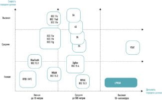
- We need the longest possible communication range so that we can connect machines from the farthest corners of a large shop.
- The device must be affordable, since it is expected to be used en masse.
After we defined the requirements, we had to decide on the wireless data transfer technology, choose the chip and assemble the device. Let's go through all of these points in order.
Basics of Wireless Networks
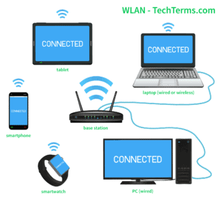
Wireless LAN (Wireless LAN, WLAN) is based on Local Area Network technology with radio-frequency communication described in IEEE 802.11 standard. This technology gives user an opportunity to feel himself as in familiar Etherne t-network using radio waves as physical medium for transmitting information. The WLAN standard of 1999 defines the frequency ranges for communication and data rates.
The structure of a wireless network is defined by a basic WLAN station, called a point of access (or sometimes a gateway), connected to a conventional Etherne t network and creating a cell with radio access. Within this cell, clients can connect to the Ethernet network via radio.
Since an access point can also act as a WLAN client, a network of multiple access points can function as a wireless network.
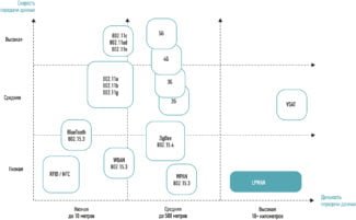
Communication using the IEEE 802.11 family of standards differs in terms of the frequencies and data rates used, from 1.2 Mbps at 2.4 GHz as described in IEEE 802.11, to 54 Mbps at 2.4 GHz in IEEE 802.11g, and from 54 Mbps at 5 GHz in IEEE 802.11a to 500 Mbps at 5 GHz in the expected IEEE 802.11n standard in the near future.
However, as frequencies and transmission speeds increase, the size of the RF cell, and therefore the maximum distance between the access point and the client, decreases. Clearly, the maximum possible distance from the access point to the client depends on the radio propagation environment within the WLAN cell where the system is used. As you know, reinforced concrete slabs, as well as a lot of interference radiated by various equipment, significantly reduce the maximum communication range. In addition, in the propagation of radio waves there is a phenomenon of interference, which also reduces the range of WLAN-systems. Depending on the radiated power and sensitivity of the receiver in an open area the maximum distance between the access point and the client can be up to 300 m, and in office buildings – up to 50 m. In factory buildings, it is usually less than 50 m.
Industrial WLAN: Increasing flexibility, lowering costs
Adopting wireless networking technology in industry not only adds significant flexibility, it can also save organizations significant amounts of money. In today's distributed control and data acquisition systems, sensors and actuators are becoming more and more "intelligent" and act as "smart controllers", providing much better control than conventional devices. Such systems are connected to the host programmable controller, using coaxial cable or twisted-pair copper as the physical layer. A significant share of the cost for such control systems is in the cabling, in this case Ethernet cabling. If, during the development or operation of such a system, it becomes necessary to make changes, expand the network, or adapt it to new equipment, it will incur additional high costs to connect new sensors or actuators, not to mention the material and time resources required to supplement and modify the topology of such a cabling network. In this situation, wireless LANs can reduce cabling costs and increase system flexibility in terms of modification capabilities. This can be illustrated in the following scenario.
First, for each individual machine or industrial robot, one access point is connected to the Ethernet port of the head controller. The agent programs (actors) can then be implemented wirelessly on the radio network created by this access point. Wireless clients are equipped with an Ethernet interface for connecting sensors and actors; in the latest developments, WLAN modules are already integrated directly into the "smart controllers", which means that it is possible to quickly make changes to the actuators. Implementation of additional sensors in such a situation will not create insurmountable problems. Another important advantage is the possibility of direct access to sensors at the network level of the OSI model (IP protocol). "Smart controllers" are often equipped with an integrated web-server, which allows to transmit the current status and diagnostic information during operation outside the hazardous area to a remote computer for subsequent analysis. Wireless adapters are already built into service and diagnostic equipment in the automotive sector, so that programs and microcode can be downloaded to the devices via the Internet directly from the office.
Read More:
